Power-Up
Power management is not that difficult with the right combination of plug strips. Before we get into the details, however, let's talk about power requirements. Using a trusty "Kill-a-Watt" power meter, we measured the total wattage for the cluster to be around 650 Watts. You should be able to use standard electrical service to power the cluster. Keep in mind, however, if you are paying the electric bill, you may not want to keep the cluster running all the time. We will present some power saving strategies in a future installment.

As far as the physical wiring is concerned, Figure Four illustrates the wiring plan we used for the wire racks. Plug strips 1 and 2 are the simple six outlet strips mentioned in the sidebar. Plug strip 3 is the Belkin SurgeMaster. Be aware that in some localities, the practice of cascading plug strips can be considered dangerous. Make sure your comply with all local codes and insurance requirements.

Rack'em and Stack'em
Now comes the fun part. Placing the nodes on the wire rack will give you a real sense of accomplishment. Unfortunately, we are are not quite done.
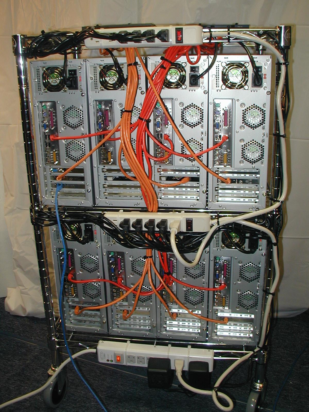
Figure Five (click here for larger version) shows the back of the cluster. As you can see, there are plenty of wires that need organizing. The white cords are the power-strips (three total), the black cords are the power cords for the nodes, the red cables are the Fast Ethernet cables, the orange cables are the Gigabit Ethernet cables. The single blue cable it the local LAN cable. Note: the middle two nodes are missing their Gigabit NICs (they were DOA). The black bands around the cables are plastic 7 inch "zip" wire ties. These are very good at bundling cables and attaching cables to the wire rack. We used white cables ties to secure the power strips. You can find these wire ties at Home Depot or Lowes.
Bundling cables is an art. We find that if we do a rough layout with a few wire ties, then go back and do a final pass it is much easier than doing it all at once. That is, we end up clipping the first set of wire ties after the second set is secure. In addition, you may have missed a wire or not include all the wires in your first pass. Also, a pair of wire cutters works real well to remove old wire ties and trim the edges off the permanent ones.
You can also see the placement of plug strips on each shelf. The top two plug strips are plain (no protection) strips. The lower strip has surge protection. To avoid large bundles of wires, we plugged the top row of nodes into the top plug strip and the second row into the the middle plug strip (only top plugs shown). The bottom plug strip has room for the switch DC power supplies and the two node plug strips. Also note, the there are extra "receptacles available" on the cluster (do not overload, however). These are important if you want to add an administration monitor to the top of the rack -- or anything else for that matter. The goal, however, was to have one power cord for the whole cluster.

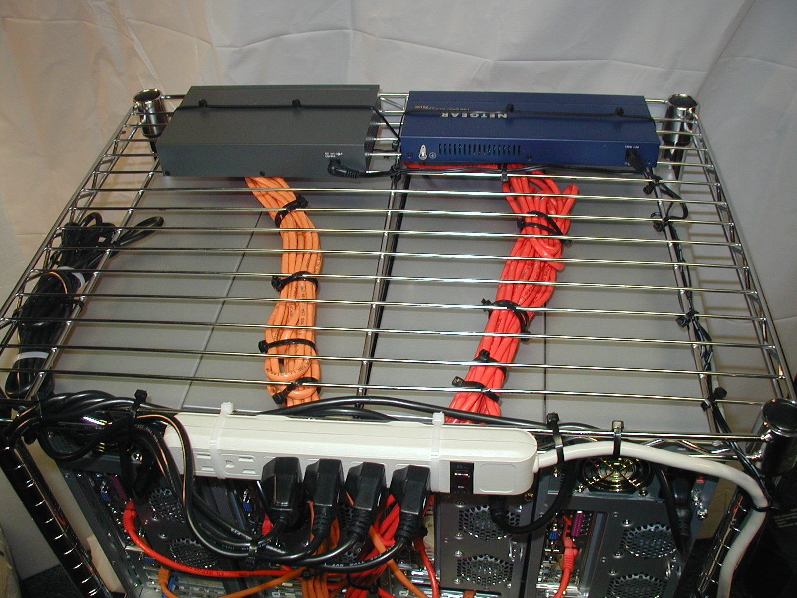
Figure Six (click here for larger version) is a top view of the cluster (from the back). First, you can see the two big cable bundles going to their respective switch. (Note: We used a Netgear FastE switch instead of the SMC switch mentioned in the Sidebar -- we had one laying around.) Use the 3-foot cables for the top row of systems and the 7-foot cables for the bottom row of systems. Also, note that the switches are secured to the rack using the trusty wire ties (connected together to form a longer tie).
Finally, you may notice that the switches face the front or the cluster. One could argue that placing them in the back would be more efficient in terms of running wires. I prefer to see the switches when the cluster is operating (such a luxury is not often the case with large clusters). Interestingly, programs often have unique communication patterns. By observing the switch lights, you can often get a feel how well a program is running. i.e. you can often see a problem by observing the communication pattern. Plus it will impress your friends.
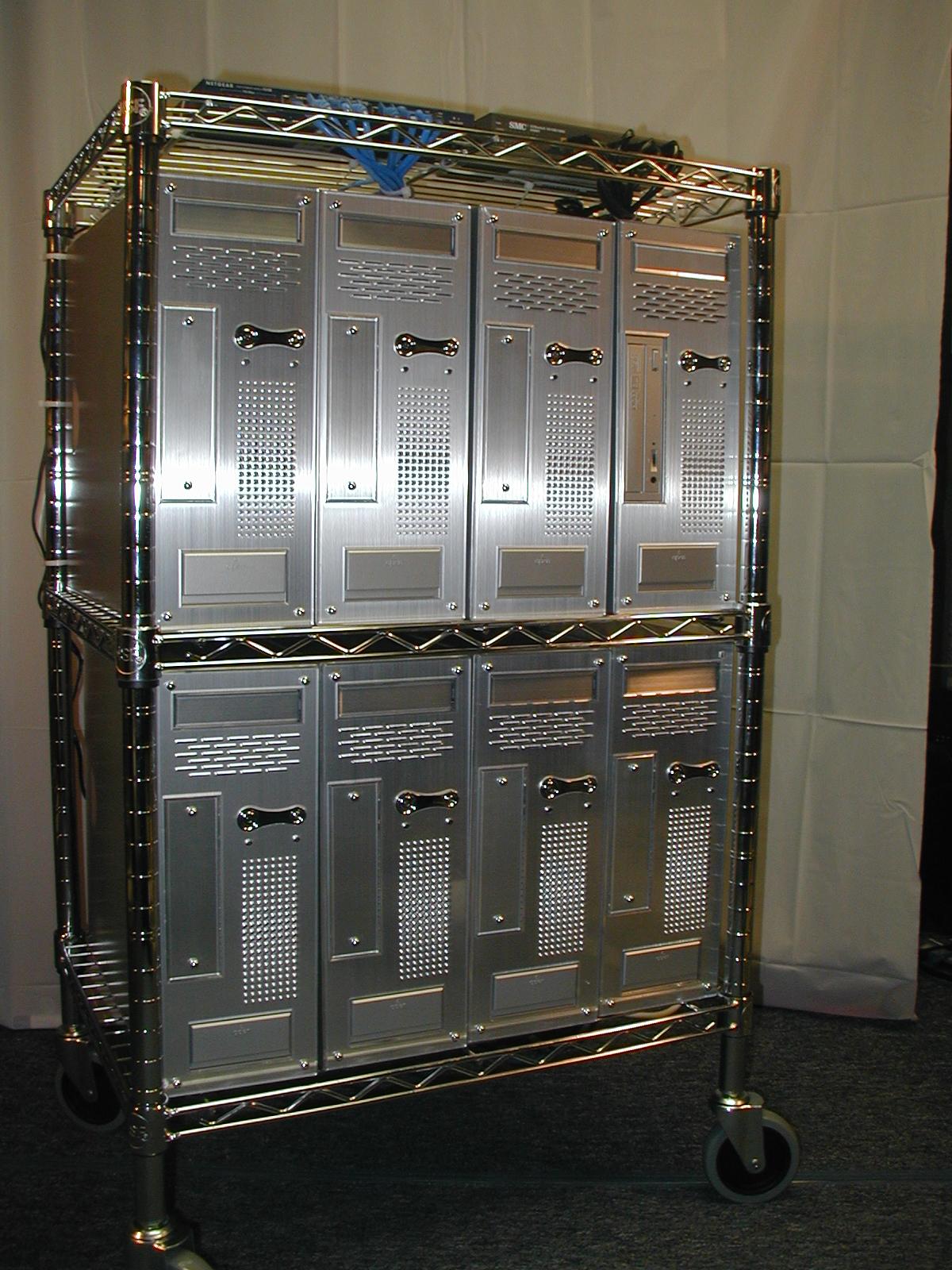
Figure Seven (click here for larger version) is a final front view of Kronos.

That Is Enough For Today Class
That is about it for now. In part two of this series, we will be configuring the BIOS and installing the software. Until then, good luck, and send us any questions. Do we still sound crazy?
| Sidebar Resources |
| Fedora Linux |
| Warewulf |
| ASRock Motherboards |
| FreeDOS Boot Diskette |
| Memtest-86 |
| PC Building Guide 1 |
| PC Building Guide 2 |
Douglas Eadline is the swinging Head Monkey at ClusterMonkey.net. Jeffrey Layton is Doug's loyal sidekick and works for Linux Networx during the day and fights cluster crime at night.

